Level 1 — Guided Motor Starter
STEP 1 Safety — Lockout/Tagout
Use the lesson controls below to isolate, lock, tag and verify zero energy before wiring. Keep the panel locked out while completing Steps 2–4.
New to meters or lockout? Try a free 2–4 minute drill first (opens in a new tab): reading a meter · where to put the probes · lockout tagout procedure
Free to play without an account. Saving your pass and getting the certificate need a free account: log in or create one, before or after you finish.
STEP 2 Field Wiring
Complete Step 1 above before wiring. Then click one terminal, then another, to install a wire.
Rest the pointer on a device (or tap its name) to see its part number, rating and wiring. The card opens only in a clear spot, never over a terminal; the details also stay here.
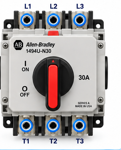
Main Disconnect Q1
480 V 3-phase IN from the plant feeder breaker → distribution block → motor fuses F2–F4 and transformer fuses F5/F6.
🔒 Lockable disconnect — the LOTO energy-isolating device (OSHA 1910.147). Lock this out to service the machine; a Stop button, the E-Stop, or the contactor is never the means of de-energization.
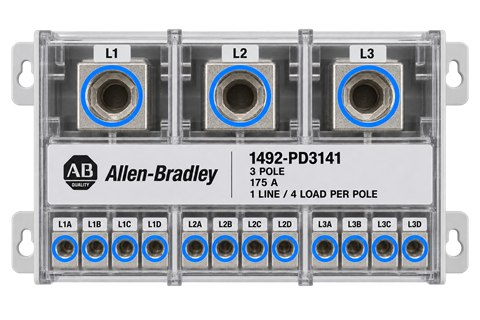
Distribution Block
1492-PD3141, 3-pole. Splits the disconnect’s load side between the motor branch (F2–F4) and the control transformer (F5/F6): one conductor per opening.

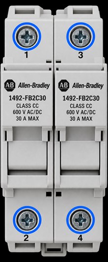
Motor Fuses F2–F4
F2 = L1 · F3 = L2 · F4 = L3. LP-CC 6 A time-delay Class CC fuses in holders rated 30 A max: about 175% of the motor’s 3.4 A, under the 300% NEC 430.52 limit for this fuse type. They clear short circuits and ground faults; running overloads are the overload relay’s job (NEC 430.32).
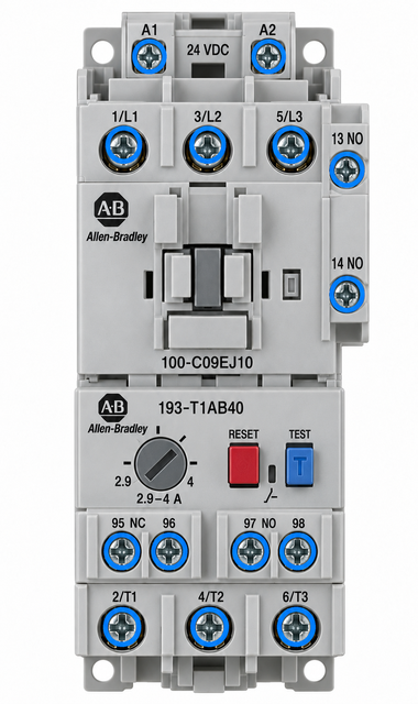
Starter M1: Contactor + Overload
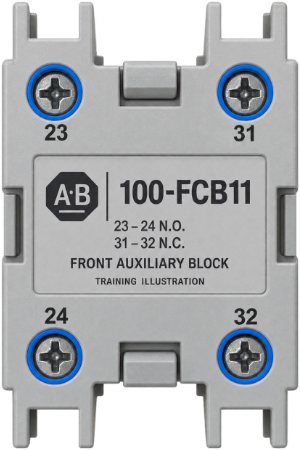
M1Contactor 100-C09EJ10 with a 193-T1AB40 overload underneath, set to the motor’s 3.4 A, manual reset. Coil code EJ = a 24 V DC electronic coil with an integrated diode (100-TD013Q p. 19). It draws 10 W on average (17 W peak) to pull in and 1.7 W to hold (p. 46): at 24 V about 0.71 A peak and 0.07 A held, within the OB16E’s 1 A per point (1756-TD002U p. 102). Power: 1/L1–5/L3 in → overload 2/T1–6/T3 → motor. On a trip, 95–96 opens the coil circuit and 97–98 closes to tell the PLC (IN-2). M1’s front aux block 100-FCB11 (23–24, drawn enlarged in the bottom row) reports M1 to the PLC (IN-3); the integral 13–14 serves only the hardwired comparison string. Auxiliary contacts per Rockwell 193-TD010A pp. 2, 7, 8.
T1 Fuses F5/F6
FNQ-R-1-8/10 (1.8 A) time-delay Class CC, one in each 480 V lead: Rockwell’s maximum for this 350 VA transformer at 480 V when the secondary is fused too (1497-TD001G, Table 13, p. 18). Not modeled here: whether it rides through the start-up inrush.
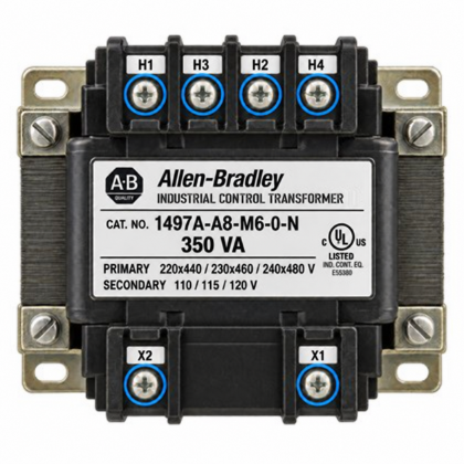
T1 Control Transformer
1497A-A8-M6-0-N, 350 VA, 480 V to 120 V: sized so its sealed load (rack supply ≤ 100 VA + 24 V supply ≤ 192 VA) stays under 350 VA (1497-TD001G p. 15). Not modeled here: its voltage during the supplies’ start-up inrush. The H2–H3 link sets the primary for 480 V. X1 is fused (F1); X2 is grounded.
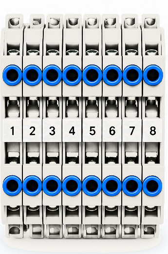
XT (X2)
White 1492-J3-W terminals, bridged, for the grounded conductor X2: in from T1, out to the 24 V supply’s N and the rack supply’s L2, and the one bond to PE. White matches X2’s white wire (NFPA 79 13.2.3).
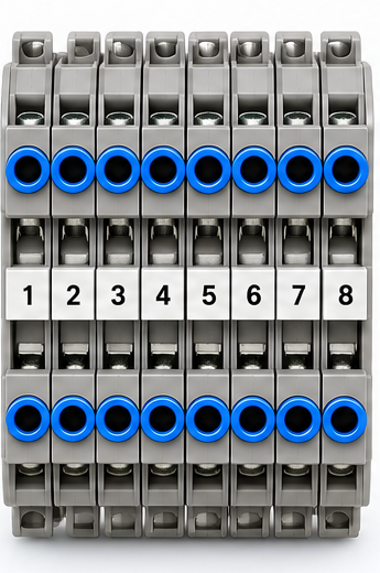
X1T (X1)
Gray 1492-J3 terminals, bridged, after F1: the fused 120 V control hot X1 splits here to the 24 V supply and the controller rack’s supply, one conductor per screw.
F1
FNQ-R-4 (4 A time-delay Class CC) on X1, ahead of BOTH supplies: the 24 V supply and the rack supply (through X1T). Rockwell’s chart allows up to 4.5 A on this 350 VA transformer’s 120 V side (1497-TD001G, Table 14, p. 18). X2 is never fused (NEC 240.22). Not modeled here: whether F1 rides through the start-up inrush of both supplies (Rockwell publishes their peak inrush, no duration; 1606-TD002H p. 30 lists a B-10 A or C-6 A minimum input protection for the 24 V supply), and the rack supply’s instructions ask for a 15 A time-delay fuse (1756-IN619G p. 5), which a real design reconciles with F1’s 4 A.
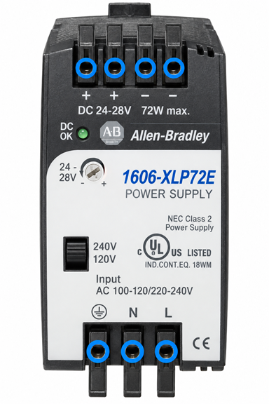
24 V DC supply
1606-XLP72E, 24 V DC 3 A, input selector at 120 V. Listed NEC Class 2 (1606-TD002H p. 39) with a SELV / PELV output (1606-AP008A): it powers the field devices, the IB16 inputs and the OB16E output group (the controller rack has its own supply, the 1756-PA72). +V → F7 → TB1 (+24 V); −V → TB2 (0 V), bonded to PE once at TB2. All pre-wired.
F7
LP-CC 4 A on the supply’s +24 V: the protection and isolation point for the 24 V distribution (TB1). Keep these Class 2 conductors apart from the power conductors that share the wireways, as a real panel must.
Controller — ControlLogix 5590 (1756-L902TS)
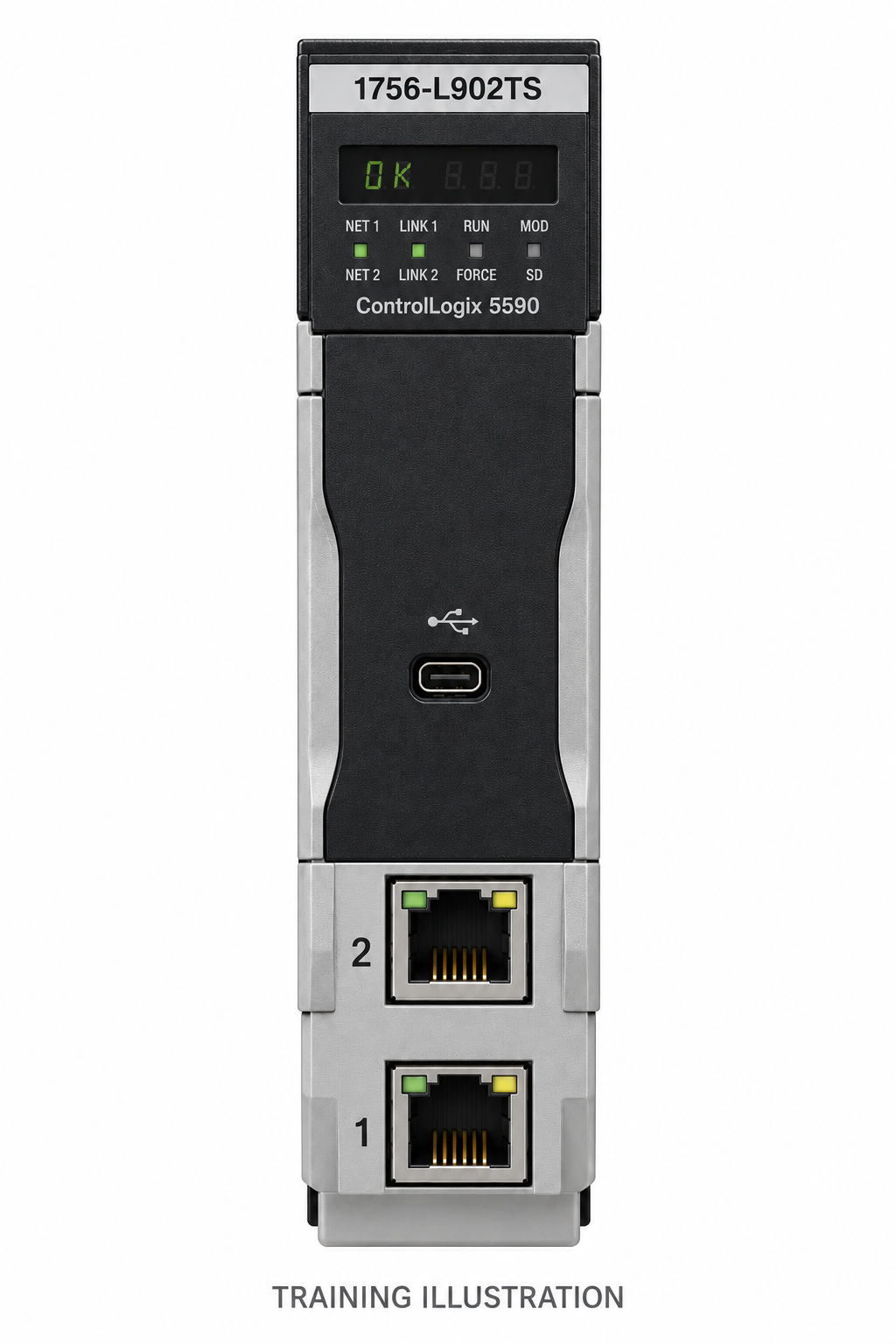
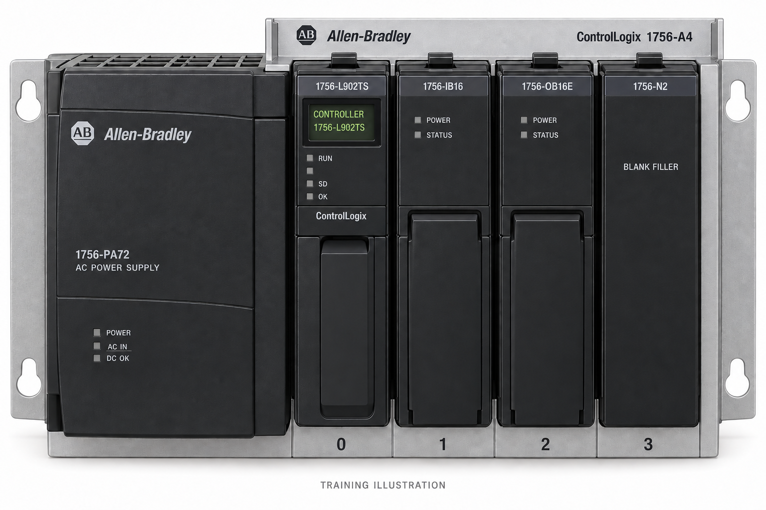
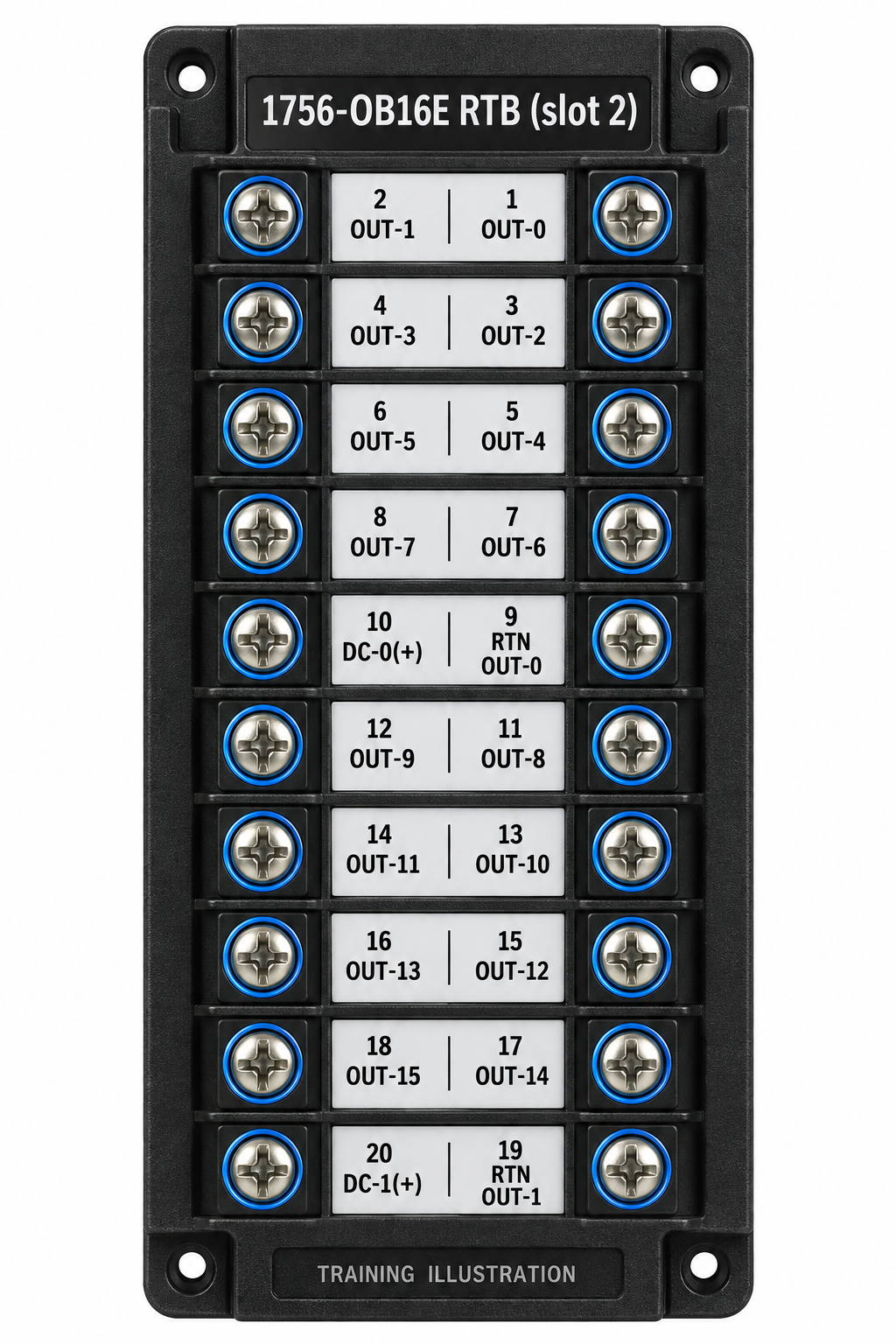
Allen-Bradley ControlLogix 5590: 1756-A4 chassis with a 1756-PA72 power supply, the 1756-L902TS controller in slot 0 (USB-C and two EtherNet/IP ports; programmed with Studio 5000 Logix Designer), a 1756-IB16 input module in slot 1, a 1756-OB16E output module in slot 2 and a 1756-N2 filler in slot 3. The input and output terminal blocks (1756-TBNH) are shown on the fronts of their modules in slots 1 and 2; the rack is enlarged for wiring. The rack has its own supply on 120 V (X1 through F1 and X1T, X2 through XT), so a fault on the 24 V field supply does not stop the controller. This lesson’s program runs in the standard task: it is not a safety function and claims no PL/SIL; the E-Stop and the overload drop the coil in hardware. Pictures: training illustrations, not photographs.
Chassis: 1756-A4 · Power supply: 1756-PA72 · Slot 0: ControlLogix 5590 controller (1756-L902TS) · Slot 1: 1756-IB16 inputs · Slot 2: 1756-OB16E outputs
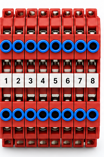
TB1 +24 V
Red feed-through terminals, bridged; fed through F7 from the 24 V supply. Field wiring lands on the top screws.
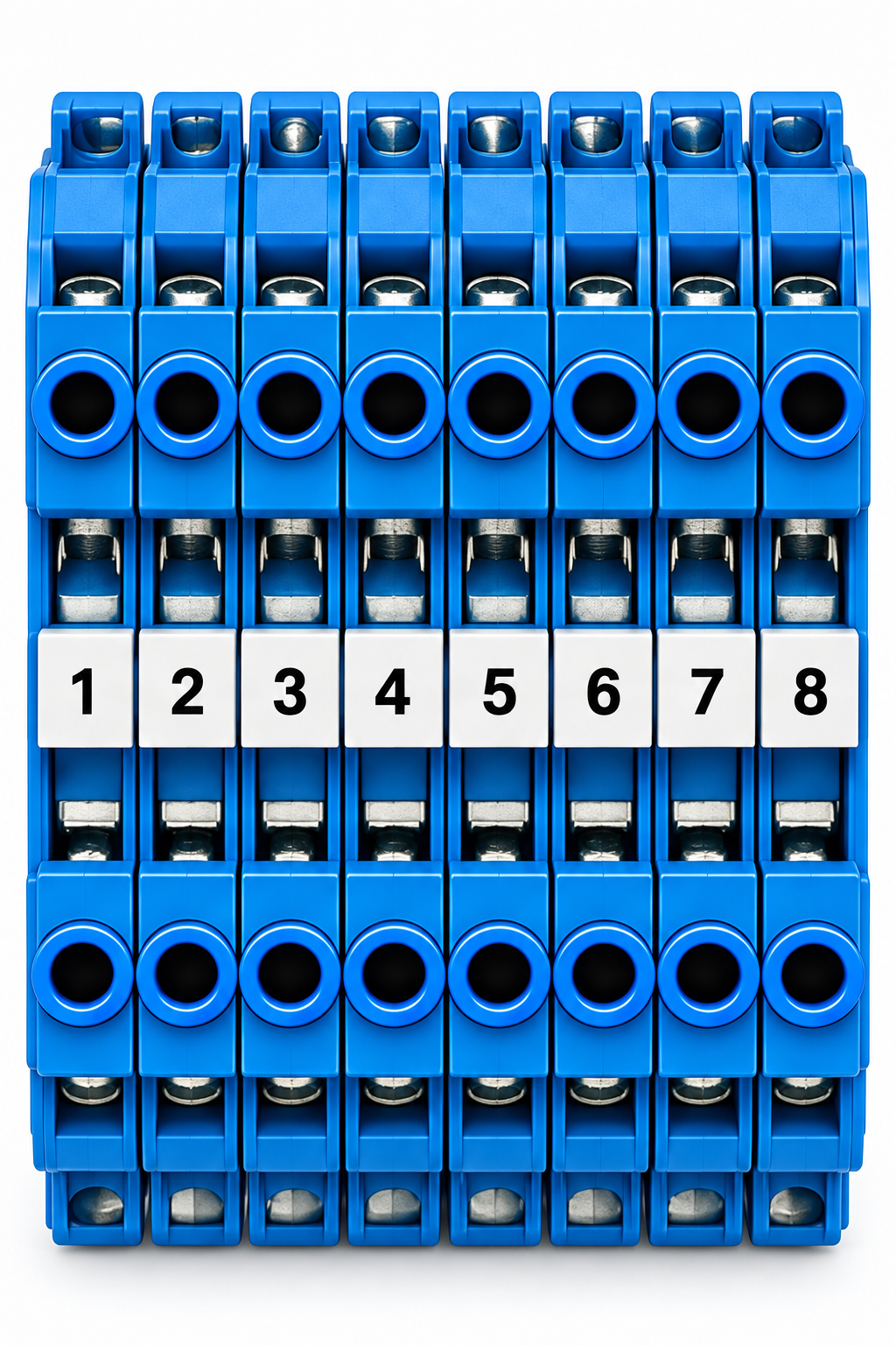
TB2 0 V
Blue feed-through terminals, bridged; fed from the supply’s −V and bonded to PE once at TB2-8.
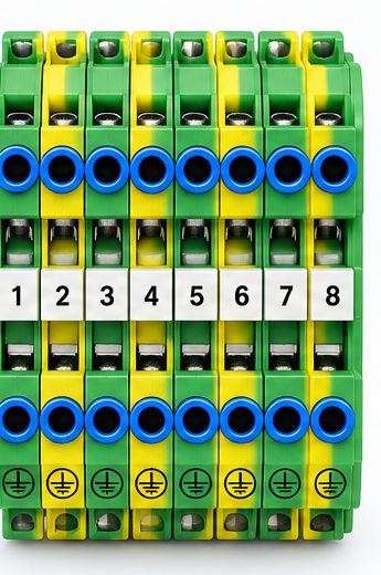
TB-PE
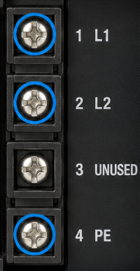
Green/yellow PE terminals on the PE bus: equipment grounding and bonding conductors only. PE carries fault current, never a normal return.
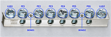
GB ground bus
The enclosure’s ground bus for the controller rack (1756-IN621E p. 12: “Each enclosure must contain a central ground bus”): the chassis PE stud (14 AWG) and the functional-earth tab (8 AWG) each on its own bolt, the PA72’s PE, and a bonding jumper to TB-PE. Bolted to the bonded backplate. Not modeled here: IN621E p. 14 asks for at least 8 AWG from the ground bus to the grounding-electrode system; here that path is the feeder’s equipment grounding conductor on TB-PE-1, sized by the feeder’s protection (NEC 250.122).
M1 aux block 100-FCB11
Drawn enlarged: Allen-Bradley 100-FCB11, a front-mounted auxiliary contact block on contactor M1 with bifurcated contacts for low-level circuits: 23–24 N.O. reports M1 to the PLC (M1_Aux, IN-3); 31–32 N.C. spare (100-TD013Q p. 31). It replaces M1’s integral 13–14 for the PLC input: that contact is rated for 17 V / 10 mA minimum, more current than a PLC input draws. Note: the IB16’s steady on-state current at 24 V is not published (about 7.6 mA estimated, not a verified minimum). Picture: training illustration.
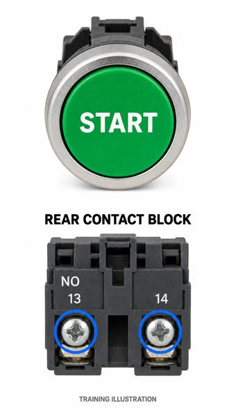
Start PB — NO
Momentary N.O. 13–14. Picture: generic 22 mm momentary pushbutton training illustration, with separate front operator and rear contact-block views. Not a photograph of a specific catalog part. Blue rings identify the depicted terminal screws.
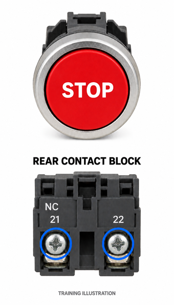
Stop PB — NC
Momentary N.C. 21–22. Picture: generic 22 mm momentary pushbutton training illustration, with separate front operator and rear contact-block views. Not a photograph of a specific catalog part. Blue rings identify the depicted terminal screws.
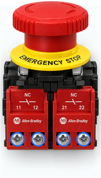
E-Stop — 2 NC
Twist-to-release, two N.C. contact blocks: 11–12 hardwired in the coil circuit (OUT-0 → 11-12 → overload 95-96 → A1), 21–22 reports to the PLC as EStop_OK (IN-4). Orderable parts: 800FM-MT44 operator + 800F-ALM latch + 2 × 800F-X01 (800F-IN016B pp. 1–2). Picture: a training illustration of such an assembly.
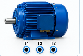
3 Phase Pump Motor
STOPPED2 hp, 460 V nameplate on the 480 V nominal supply, 3Φ, 60 Hz · full-load current 3.4 A (NEC Table 430.250, a training value) · PE = green/yellow equipment grounding conductor to TB-PE
Option A — PLC wiring (the accepted solution)
Before wiring: lock out the panel and verify it is dead using the lesson’s energy controls. Each numbered connection below is one wire.
TB1 supplies +24 V DC; TB2 is the 0 V DC return. Use a different unused screw for every connection to either strip. Keep one conductor per screw. The power supplies, controller-rack power and protective-earth wiring are already installed.
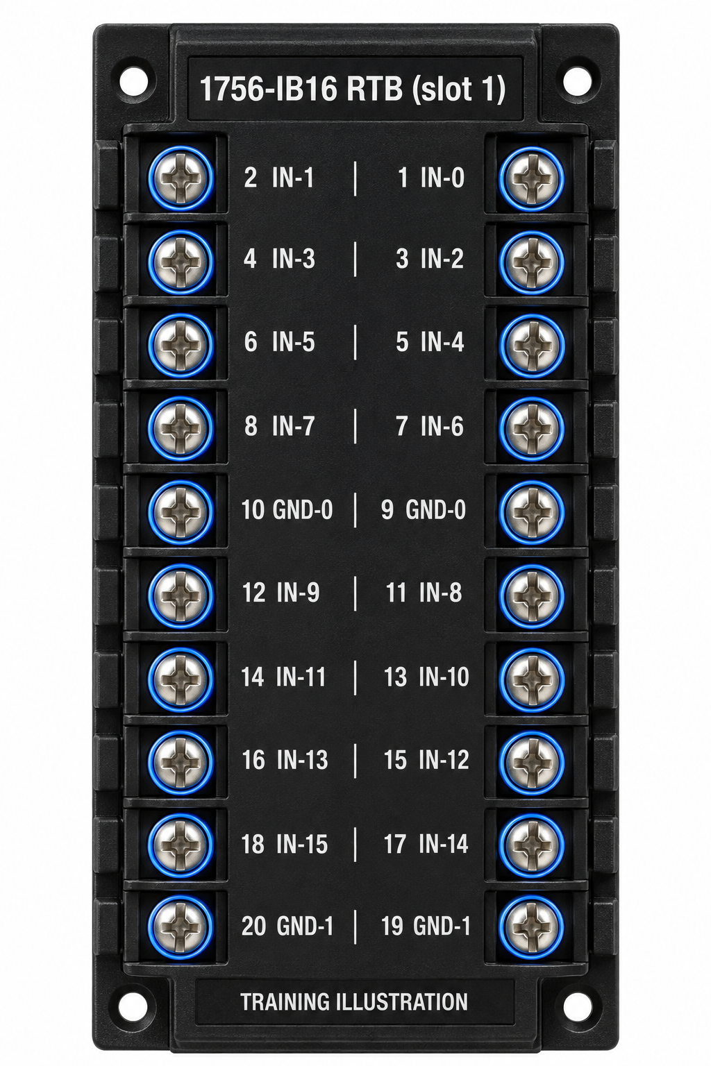
Find the right module: the enlarged IB16 input terminal block is for sensor and button signals. The enlarged OB16E output terminal block is for output power and the contactor command. A pin number identifies a physical screw; IN/OUT identifies its channel. The PLC address is shown separately for reference.
1. Start pushbutton
- Connect an unused TB1 (+24 V DC) terminal to Start terminal 13.
- Connect Start terminal 14 to IB16 pin 1, labeled IN-0.
What it does: Pressing Start closes contact 13–14 and turns on Start_PB.
PLC address: Local:1:I.Data.0
2. Stop pushbutton
- Connect an unused TB1 (+24 V DC) terminal to Stop terminal 21.
- Connect Stop terminal 22 to IB16 pin 2, labeled IN-1.
What it does: Contact 21–22 is closed while Stop is released. Pressing Stop opens it and turns off Stop_PB.
PLC address: Local:1:I.Data.1
3. Overload trip feedback
- Connect an unused TB1 (+24 V DC) terminal to Overload terminal 97.
- Connect Overload terminal 98 to IB16 pin 3, labeled IN-2.
What it does: Contact 97–98 closes when the overload trips, turning on Motor_OL_Trip. This is the trip signal; terminals 95–96 are used separately in step 8.
PLC address: Local:1:I.Data.2
4. Contactor run feedback
- Connect an unused TB1 (+24 V DC) terminal to M1 front auxiliary block terminal 23.
- Connect M1 front auxiliary block terminal 24 to IB16 pin 4, labeled IN-3.
What it does: Use the separate 100-FCB11 auxiliary block, not M1’s integral terminals 13–14. Contact 23–24 closes when M1 pulls in, turning on M1_Aux.
PLC address: Local:1:I.Data.3
5. E-Stop status feedback
- Connect an unused TB1 (+24 V DC) terminal to E-Stop terminal 21.
- Connect E-Stop terminal 22 to IB16 pin 5, labeled IN-4.
What it does: Contact 21–22 is closed while the E-Stop is released, so EStop_OK is on. The separate contact 11–12 is used in step 8.
PLC address: Local:1:I.Data.4
6. Input-module common
- Connect IB16 pin 9 or pin 10, labeled GND-0 to an unused TB2 (0 V DC) terminal.
What it does: Pins 9 and 10 are internally connected. Use either one for this connection. GND-0 is the return for inputs IN-0 through IN-7.
7. Output-module power
- Connect an unused TB1 (+24 V DC) terminal to OB16E pin 10, labeled DC-0(+).
- Connect OB16E pin 9, labeled RTN OUT-0 to an unused TB2 (0 V DC) terminal.
What it does: Output group 0 needs both its +24 V supply and its 0 V return.
8. Contactor coil and stop circuit
- Connect OB16E pin 1, labeled OUT-0 to E-Stop terminal 11.
- Connect E-Stop terminal 12 to Overload terminal 95.
- Connect Overload terminal 96 to M1 coil terminal A1.
- Connect M1 coil terminal A2 to an unused TB2 (0 V DC) terminal.
What it does: These four wires form the coil circuit. Pressing the E-Stop opens 11–12; an overload trip opens 95–96. Either opening drops the contactor independently of the PLC program.
PLC address: Local:2:O.Data.0
9. Motor leads
- Connect Overload terminal 2/T1 to Motor terminal T1.
- Connect Overload terminal 4/T2 to Motor terminal T2.
- Connect Overload terminal 6/T3 to Motor terminal T3.
What it does: Connect the motor to the overload’s outgoing terminals so motor current passes through the overload.
After wiring: restore power through the lesson’s energy controls, wait for the controller to finish starting, then switch the PLC to RUN before pressing Start. Level 1 includes a supplied program; you do not need to write it.
Why the supplied program uses run feedback and restart permission
Why seal in through M1_Aux? When the E-Stop or the overload opens the coil circuit, the contactor drops out and its aux contacts open, so the rung loses its seal. Why a restart permission? A Start that is held while Stop or the E-Stop is released, the overload is reset or the power comes back would otherwise start the motor again at once. Rung 1 of the supplied program (Start_Permit) grants the permission only after Start has been seen released, and Stop, the E-Stop, a trip — or M1 dropping out by itself after a confirmed run (rung 0, Run_Confirmed) — takes it away. After wiring: switch the PLC to RUN before pressing Start (after power returns, the controller first starts up: shortened to 4 s here).
Option B — hardwired comparison (not accepted for completion)
This comparison uses a different circuit. Follow Option A above to complete Level 1.
- Connect TB1 (+24 V DC) to E-Stop 11.
- Connect E-Stop 12 to Stop 21.
- Connect Stop 22 to Start 13.
- Connect Start 14 to Overload 95.
- Connect Overload 96 to M1 A1.
- Connect M1 A2 to TB2 (0 V DC).
- Connect M1 integral auxiliary terminal 13 to Start 13.
- Connect M1 integral auxiliary terminal 14 to Start 14.
The integral auxiliary contact 13–14 is across Start for seal-in. Connect the three motor leads as in step 9.
This comparison has no restart permission: holding Start while releasing the E-Stop, resetting the overload or restoring power can restart the motor. A hardwired design needs additional restart controls; this lesson accepts the PLC solution.
STEP 3 PLC Program — ControlsTrainer 5000
The supplied program is loaded: rung 0 confirms that M1 really pulled in (Run_Confirmed), rung 1 is the restart permission, rung 2 runs the motor. You do not have to write PLC logic here — read it, try changes in PROGRAM mode, or load it again. The controller executes the rungs from top to bottom.
New to ladder logic? Free 3–5 minute drills (open in a new tab): XIC, XIO and OTE · seal-in (start/stop) circuit · quiz buzzer lockout
| Tag | Alias for | Type |
|---|---|---|
| Start_PB | Local:1:I.Data.0 | IB16 input IN-0 (pin 1) — Start 13–14 (N.O.) |
| Stop_PB | Local:1:I.Data.1 | IB16 input IN-1 (pin 2) — Stop 21–22 (N.C.) |
| Motor_OL_Trip | Local:1:I.Data.2 | IB16 input IN-2 (pin 3) — overload 97–98 (N.O.) |
| M1_Aux | Local:1:I.Data.3 | IB16 input IN-3 (pin 4) — M1 aux block 23–24 (N.O.) |
| EStop_OK | Local:1:I.Data.4 | IB16 input IN-4 (pin 5) — E-Stop 21–22 (N.C.) |
| Motor_Run | Local:2:O.Data.0 | OB16E output OUT-0 (pin 1), sourcing |
| Start_Permit | — | Internal BOOL tag |
| Run_Confirmed | — | Internal BOOL tag (M1 seen in while Motor_Run is on) |
N.O. / N.C. on the device ≠ XIC / XIO in the program
N.O. and N.C. describe the device at rest (nobody pressing it, nothing tripped). XIC and XIO test a bit: XIC (examine if closed) passes when the bit is 1; XIO (examine if open) passes when the bit is 0. The input bit is 1 whenever current reaches that input — so read the device first, then the bit, then choose the instruction. An N.C. device does not automatically mean XIO.
| Device | State | Contact | Input bit | XIC | XIO |
|---|---|---|---|---|---|
| Stop (N.C. 21–22) → IN-1 | released | closed | 1 | true | false |
| pressed | open | 0 | false | true | |
| Overload (N.O. 97–98) → IN-2 | healthy | open | 0 | false | true |
| tripped | closed | 1 | true | false | |
| E-Stop (N.C. 21–22) → IN-4 | released | closed | 1 | true | false |
| pressed | open | 0 | false | true |
So the Motor_Run rung uses XIC Stop_PB and XIC EStop_OK (true until pressed) and XIO Motor_OL_Trip (true until the overload trips). The overload’s other contact, 95–96 (N.C.), is not an input at all: it sits in the coil circuit and drops the contactor on a trip whatever the program does. A broken status wire reads 0: for Stop and E-Stop that stops the motor, which is why stop signals are wired N.C.
STEP 4 I/O Status
Review the input and output assignments while locked out. Live indications remain off until power is restored in Step 5; return here to observe them during the test.
| Address | Tag | State |
|---|---|---|
| Local:1:I.Data.0 | Start_PB | OFF |
| Local:1:I.Data.1 | Stop_PB | ON |
| Local:1:I.Data.2 | Motor_OL_Trip | OFF |
| Local:1:I.Data.3 | M1_Aux | OFF |
| Local:1:I.Data.4 | EStop_OK | ON |
| Local:2:O.Data.0 | Motor_Run | OFF |
| (internal) | Start_Permit | 0 |
| (internal) | Run_Confirmed | 0 |
Goal
Switch the PLC to RUN, then press Start. The rung seals in through M1’s front aux block 23–24 (M1_Aux on IN-3). Press Stop, press the E-Stop or trip the overload to drop the motor out. Then try it with Start held: hold the green Start button on its picture while you release Stop or the E-Stop, or reset the overload — the supplied program’s restart permission keeps the motor stopped until Start is released and pressed again.
Stop circuit
The E-Stop’s first contact block (11–12, N.C.) and the overload’s 95–96 (N.C.) are wired in series with the contactor coil: OUT-0 → 11–12 → 95–96 → A1. Either one drops the contactor whatever the PLC program is doing. The E-Stop’s second block (21–22) and the overload’s 97–98 only report to the PLC, so the program can withhold its command until the operator restarts deliberately.
What this lesson does and does not show: releasing the E-Stop does not start the motor by itself: the contactor’s seal is lost, and the Start_Permit rung withholds the command until Start has been released and pressed again — even if Start was held through the release, a Stop, an overload reset or a power return. This is ordinary PLC logic with a two-contact E-Stop, not a safety-rated circuit: a welded contactor or a failed output is not detected. Where the risk assessment calls for it, a monitored safety relay does this job (Level 6). The ordinary Stop drops the permission too, so a Start held through a Stop does not restart the motor either. So does M1 dropping out by itself after a confirmed run (its output lost DC-0(+) or RTN OUT-0, a wire came off): rung 0 remembers that M1 had pulled in, so when M1’s aux contact opens while the command is still on, rung 1 takes the permission away and the motor does not restart when the supply returns. This program has no timer: a start pressed while the output has no supply waits as long as Start is held (Level 2 adds a 150 ms pickup check that aborts it); a momentary press leaves nothing pending. The overload’s 97–98 is N.O., so if its status wire is broken the PLC cannot see a trip — 95–96 still stops the motor, but check that input when you commission the panel. A short on the 24 V supply drops the field inputs and the output, but not the controller: the rack has its own supply (the PA72 on 120 V). A wire from +24 V to a PE terminal is the same short, because 0 V is bonded to PE. If the output OUT-0 switches onto a short, the OB16E’s electronic fuse turns its group off and stays tripped until it is reset (Reset fuse, from Logix Designer online); this trainer refuses that reset while the program still commands the output on. If M1’s aux contact makes the short, this trainer holds the 24 V supply off until you rewire or switch the panel off and on. The controller’s start-up after a power loss is shortened to 4 s here. A short on the 120 V or 480 V side opens the protection in its path: on the motor’s branch that is F2–F4, and only the motor loses power; anywhere else it is the protection ahead of both supplies (F1, F5/F6 or the feeder’s own), so the controller loses power too. Which device opens first in a real panel depends on how the protection is coordinated. This trainer keeps it open until you lock out and restore power, which stands for finding the fault and replacing the fuse.
STEP 5 Restore Power & Test the Machine
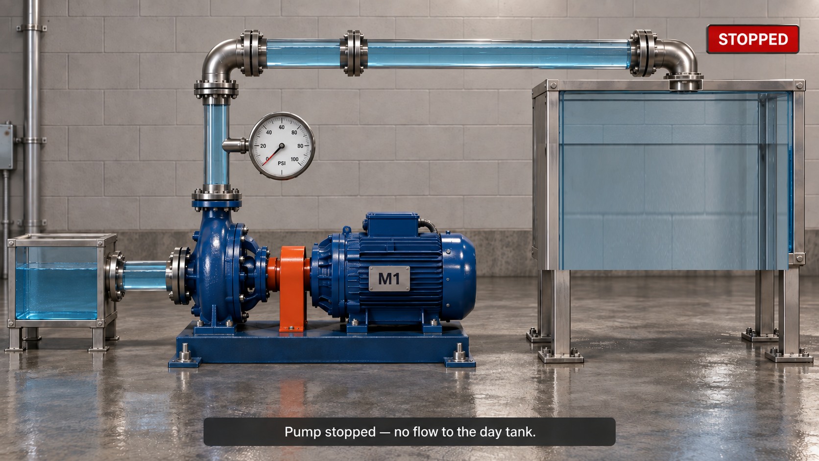
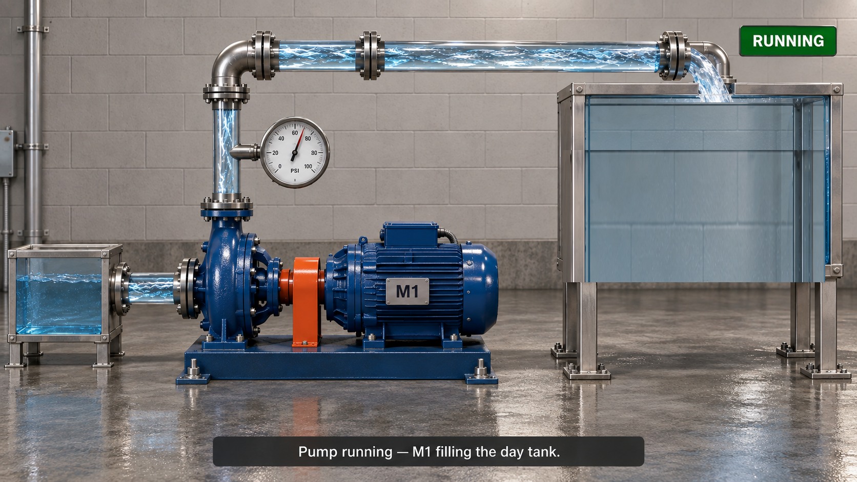
The starter you wire drives this pump. Bring the motor online to fill the day tank.
STEP 6 Check Completion
When your machine operates correctly, check your completion requirements. The motor run on the PLC wiring has to come after the last lockout, short or protection trip, overload trip, wiring change and PROGRAM/RUN change (each one clears it), and the panel has to be powered with nothing tripped and the E-Stop released when you check.