Level 1 — Guided Motor Starter
Field Wiring
Lock out the main disconnect first (panel below). Then click one terminal, then another, to install a wire.
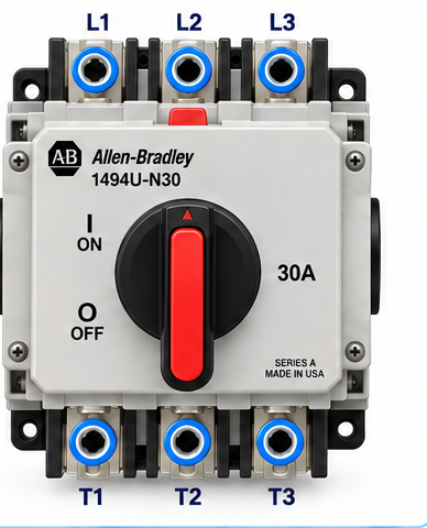
Main Disconnect — 3-Phase Line In
3-phase power IN → factory-fed to the motor branch. Its load side also feeds control transformer T1 (mounted above this panel), which supplies the 24 V supply’s 120 V control power.
🔒 Lockable disconnect — the LOTO energy-isolating device (OSHA 1910.147). Lock this out to service the machine; a Stop button, the E-Stop, or the contactor is never the means of de-energization.
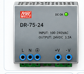
24 VDC Power Supply
L / N = 120 V control power X1 / X2, pre-wired from control transformer T1 above this panel. Opening the main disconnect removes it.
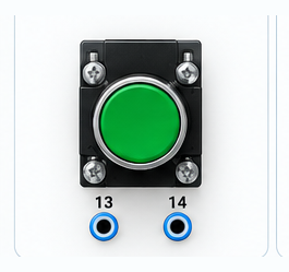
Start PB — NO
Stop PB — NC
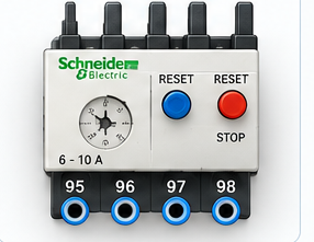
Overload — NC
95–96 = NC (wire these) · 97–98 = NO (spare)
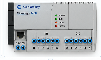
PLC — Allen-Bradley MicroLogix 1400
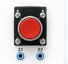
E-Stop — NC Safety Contact
21–22 = NC safety contact · hardwired in series with the coil

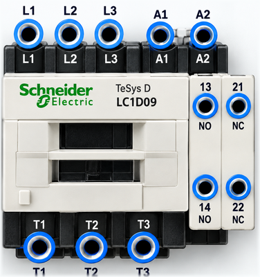
Contactor M1
M1T1–T2–T3 (load) → wire to motor T1–T2–T3
3 Phase Motor
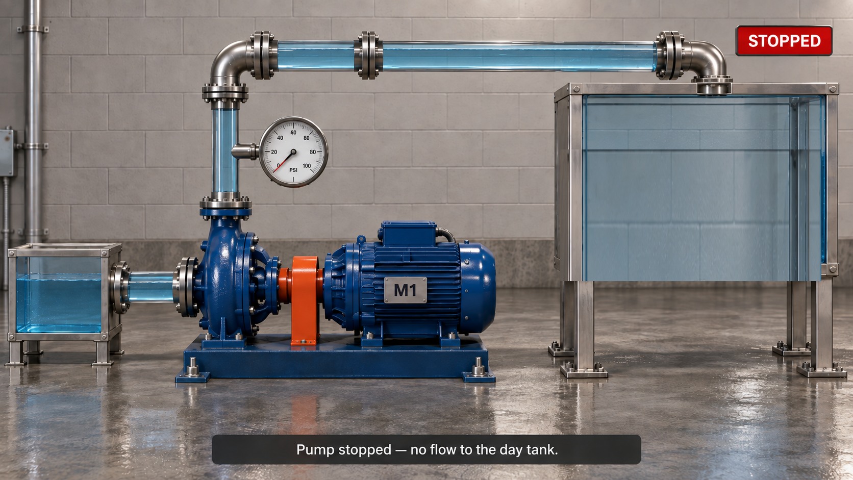
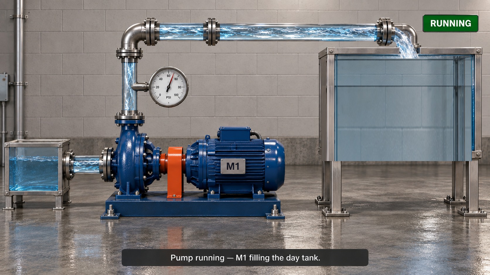
STOPPEDMotor receives 3-phase power from contactor M1 · PE = green/yellow equipment ground bonds the frame
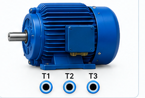
Machine — M1 Transfer Pump
The starter you wire drives this pump. Bring the motor online to fill the day tank.
Ladder Logic Editor
Build the program yourself. The PLC executes the rungs from top to bottom.
| Tag | Address | Type |
|---|---|---|
| Start_PB | I:0/0 | Input |
| Stop_PB | I:0/1 | Input |
| Motor_OL | I:0/2 | Input |
| Motor_Run | O:0/0 | Output |
I/O Status
| Address | Tag | State |
|---|---|---|
| I:0/0 | Start_PB | OFF |
| I:0/1 | Stop_PB | ON |
| I:0/2 | Motor_OL | ON |
| O:0/0 | Motor_Run | OFF |
Goal
Switch the PLC to RUN, then press Start. The output should seal itself in. Press Stop or trip the overload to drop the motor out.
Safety Circuit
The E-Stop is a normally-closed contact hardwired in series with the contactor coil (O:0/0 → E-Stop 21, E-Stop 22 → M1 A1). Pressing it drops the contactor no matter what the PLC program is doing — the safety stop does not depend on the ladder logic. Twist to release, then Start again to recover.
Training simplification: in this simulator, releasing the E-Stop does not restart the motor — a new Start press is needed. On a real machine the PLC program can only drop its run seal if the PLC can see the E-Stop (a second E-Stop contact wired to a PLC input, or a safety relay). This drawing leaves that connection out.
Complete Level 1
When your machine operates correctly, check your completion requirements.